Prøve GULL - Gratis
Beam Compass
Model Engineer
|4624
I made the locking rings (part 3) and the adjusting ring (part 8) from 1 inch diameter aluminium turned down to 22mm diameter for a length of at least 40mm to make all four rings.

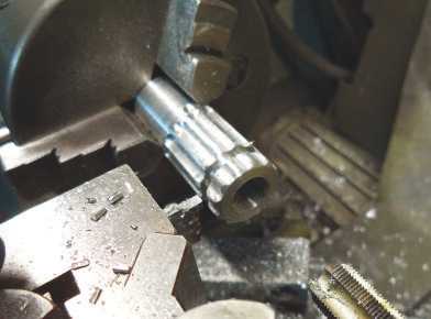
These rings would normally be knurled but instead of knurling I decided to mill 12 finger grips along the length of the bar with a ¼ inch bull nosed slot drill using the spin indexer. The bar was then loaded back into the lathe, the smaller M3 hole for the adjusting ring drilled and tapped first, some neat chamfers added and then parted off to length. Then I drilled and tapped the locking rings ½ inch x 32ME, chamfered them and parted them off to length (photos 9 and 10).
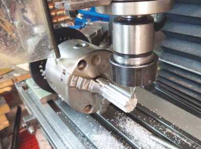
Here’s another little trick for putting the chamfers on the rings. Make yourself a form tool, use it to chamfer the front then, before you part off, chamfer the back. At the same time, you will be chamfering the front of the next ring this way you won’t have the problem of trying to chuck the thin part for chamfering the back (photo 11).
Denne historien er fra 4624-utgaven av Model Engineer.
Abonner på Magzter GOLD for å få tilgang til tusenvis av kuraterte premiumhistorier og over 9000 magasiner og aviser.
Allerede abonnent? Logg på
FLERE HISTORIER FRA Model Engineer

Model Engineer
WORKSHOP TIP - Boring Eccentrics
I am making a 1 inch Minnie traction engine and have arrived at the machining of the eccentric straps.
3 mins
4635

Model Engineer
Wenford A 7¼ Inch Gauge 2-4-0 Beattie Well Tank
The stage has now been reached where the well tank body can be completed but beforehand there are some internal details to add.
4 mins
4635

Model Engineer
Vertical Boiler Locomotives
Vertical Boiler Locomotives
4 mins
4635

Model Engineer
Union Nuts, and How to Make Them
These are quite different from those commercially available and are made from copper
3 mins
4635

Model Engineer
SHOWCASE Paul's Engine
One day my son Paul came to me and asked if we could make something in my workshop, so that he could learn engineering processes.
1 min
4635

Model Engineer
CLUB NEWS
My secret’s out!
9 mins
4635

Model Engineer
Building Dancer - The Boiler
Dancer needed a boiler that would be somewhat larger than the size permitted under the Model Engineering exemptions in the New Zealand regulations.
10 mins
4635

Model Engineer
An Inverted ‘Ross Yoke' Watercooled Stirling Engine
As with all my hot air engines they are cheap to build, mostly from scrap
5 mins
4635

Model Engineer
A Draught Proposal
A Draught Proposal
12 mins
4635

Model Engineer
A Boiler Feed Pump
A Boiler Feed Pump
2 mins
4635
Translate
Change font size