
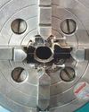
These rings would normally be knurled but instead of knurling I decided to mill 12 finger grips along the length of the bar with a ¼ inch bull nosed slot drill using the spin indexer. The bar was then loaded back into the lathe, the smaller M3 hole for the adjusting ring drilled and tapped first, some neat chamfers added and then parted off to length. Then I drilled and tapped the locking rings ½ inch x 32ME, chamfered them and parted them off to length (photos 9 and 10).
Here’s another little trick for putting the chamfers on the rings. Make yourself a form tool, use it to chamfer the front then, before you part off, chamfer the back. At the same time, you will be chamfering the front of the next ring this way you won’t have the problem of trying to chuck the thin part for chamfering the back (photo 11).
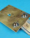
You can make the beams (part 5) any length. I made mine 300mm and, when they are screwed together, I can draw 1m diameter circles, although I doubt very much I’ll ever need to draw a circle that size. All you have to do is turn and thread one end M5 and drill and tap the other M5. The second beam only needs the male thread (photo 12).
This story is from the 4624 edition of Model Engineer.
Start your 7-day Magzter GOLD free trial to access thousands of curated premium stories, and 8,500+ magazines and newspapers.
Already a subscriber ? Sign In
This story is from the 4624 edition of Model Engineer.
Start your 7-day Magzter GOLD free trial to access thousands of curated premium stories, and 8,500+ magazines and newspapers.
Already a subscriber? Sign In
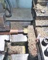
WORKSHOP TIP - Boring Eccentrics
I am making a 1 inch Minnie traction engine and have arrived at the machining of the eccentric straps.
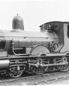
Wenford A 7¼ Inch Gauge 2-4-0 Beattie Well Tank
The stage has now been reached where the well tank body can be completed but beforehand there are some internal details to add.
Vertical Boiler Locomotives
Vertical Boiler Locomotives
Union Nuts, and How to Make Them
These are quite different from those commercially available and are made from copper
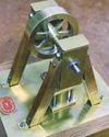
SHOWCASE Paul's Engine
One day my son Paul came to me and asked if we could make something in my workshop, so that he could learn engineering processes.
CLUB NEWS
My secret’s out!

Building Dancer - The Boiler
Dancer needed a boiler that would be somewhat larger than the size permitted under the Model Engineering exemptions in the New Zealand regulations.
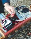
An Inverted ‘Ross Yoke' Watercooled Stirling Engine
As with all my hot air engines they are cheap to build, mostly from scrap
A Draught Proposal
A Draught Proposal
A Boiler Feed Pump
A Boiler Feed Pump