
Completing the well tank body
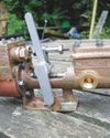
The stage has now been reached where the well tank body can be completed but beforehand there are some internal details to add. The bottom plate includes an angled section at the rear which will leave the tank partially open for a closing section to be added last - see fig 5.
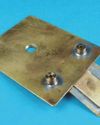
So, cut out the bottom plate from 1⁄16 inch thick brass and put the bend in it to wrap around the corner. It is best if any sharp corners on the existing body sides are slightly radiused so the bend will nestle close to it rather than try to form a severe crease in the brass plate. Leave an external margin around the tank body for the silver soldering process as discussed for the bunker tank.
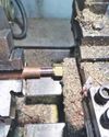
Before the plate is added to the body, a drain plug boss is required near the bend and three small brass or bronze blocks need to be added to the inside for the two water valve fixing bolts and the lower tank fastening position which engages with a bracket on the rear axle spring housing. These blocks are all 3⁄16 inch thick and are held in place with 1⁄16 inch copper rivets. Take care to ensure that the two blocks at the sides will allow the plate to fit onto the body. Add silver solder to all three and, should there be any distortion of the plate as the heat relieves the stress after the bending operation, it can be readily straightened at this stage.
This story is from the 4635 edition of Model Engineer.
Start your 7-day Magzter GOLD free trial to access thousands of curated premium stories, and 8,500+ magazines and newspapers.
Already a subscriber ? Sign In
This story is from the 4635 edition of Model Engineer.
Start your 7-day Magzter GOLD free trial to access thousands of curated premium stories, and 8,500+ magazines and newspapers.
Already a subscriber? Sign In
WORKSHOP TIP - Boring Eccentrics
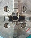
I am making a 1 inch Minnie traction engine and have arrived at the machining of the eccentric straps.
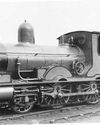
Wenford A 7¼ Inch Gauge 2-4-0 Beattie Well Tank
The stage has now been reached where the well tank body can be completed but beforehand there are some internal details to add.
Vertical Boiler Locomotives
Vertical Boiler Locomotives
Union Nuts, and How to Make Them
These are quite different from those commercially available and are made from copper
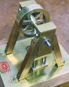
SHOWCASE Paul's Engine
One day my son Paul came to me and asked if we could make something in my workshop, so that he could learn engineering processes.
CLUB NEWS
My secret’s out!

Building Dancer - The Boiler
Dancer needed a boiler that would be somewhat larger than the size permitted under the Model Engineering exemptions in the New Zealand regulations.

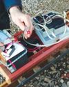
An Inverted ‘Ross Yoke' Watercooled Stirling Engine
As with all my hot air engines they are cheap to build, mostly from scrap
A Draught Proposal
A Draught Proposal
A Boiler Feed Pump
A Boiler Feed Pump